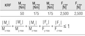
Simplified method for determining the maximum permissible load for the Roller Guides of a KRF:
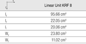
The mass moments of inertia of the profile provide the basis for calculating the deflection:

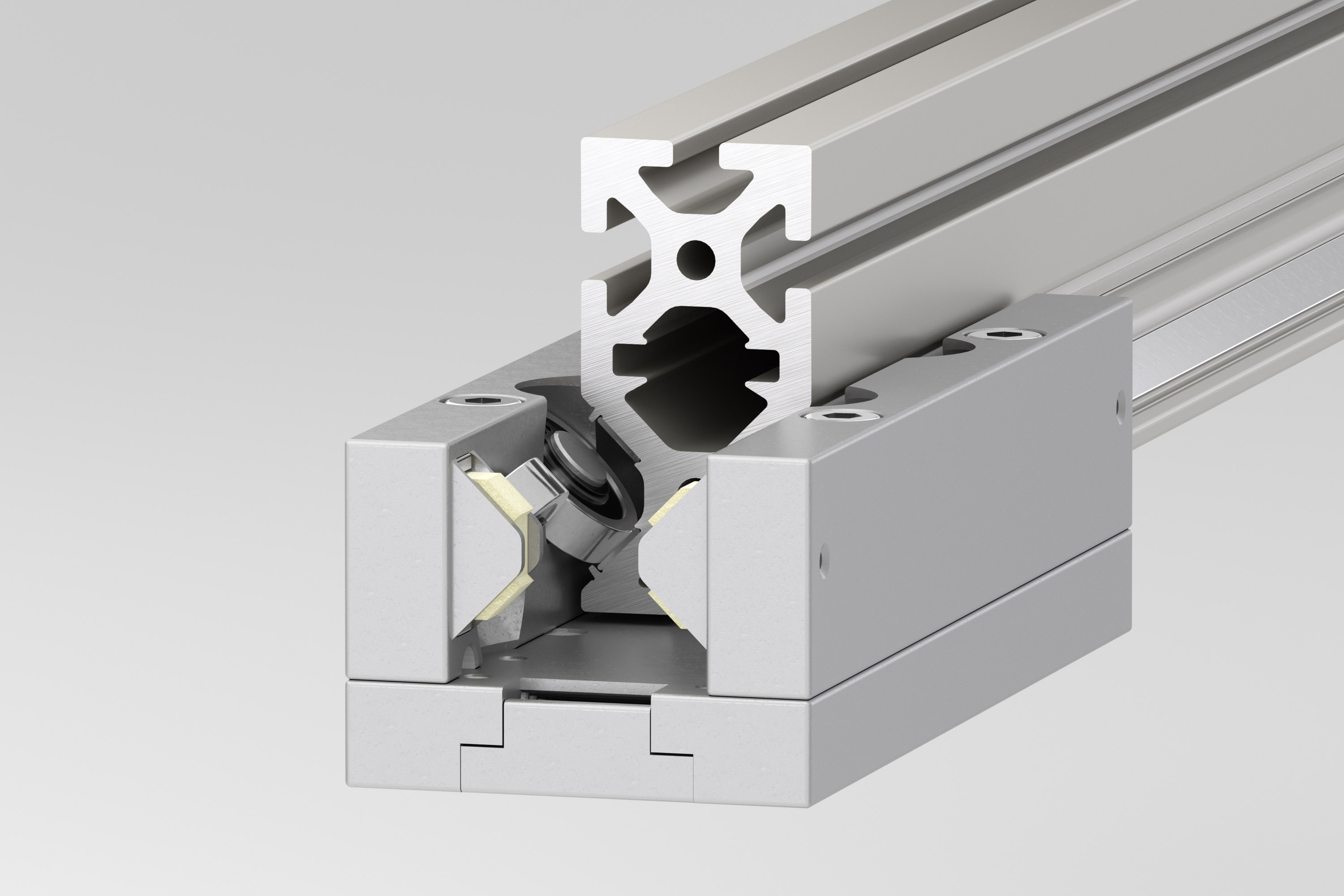
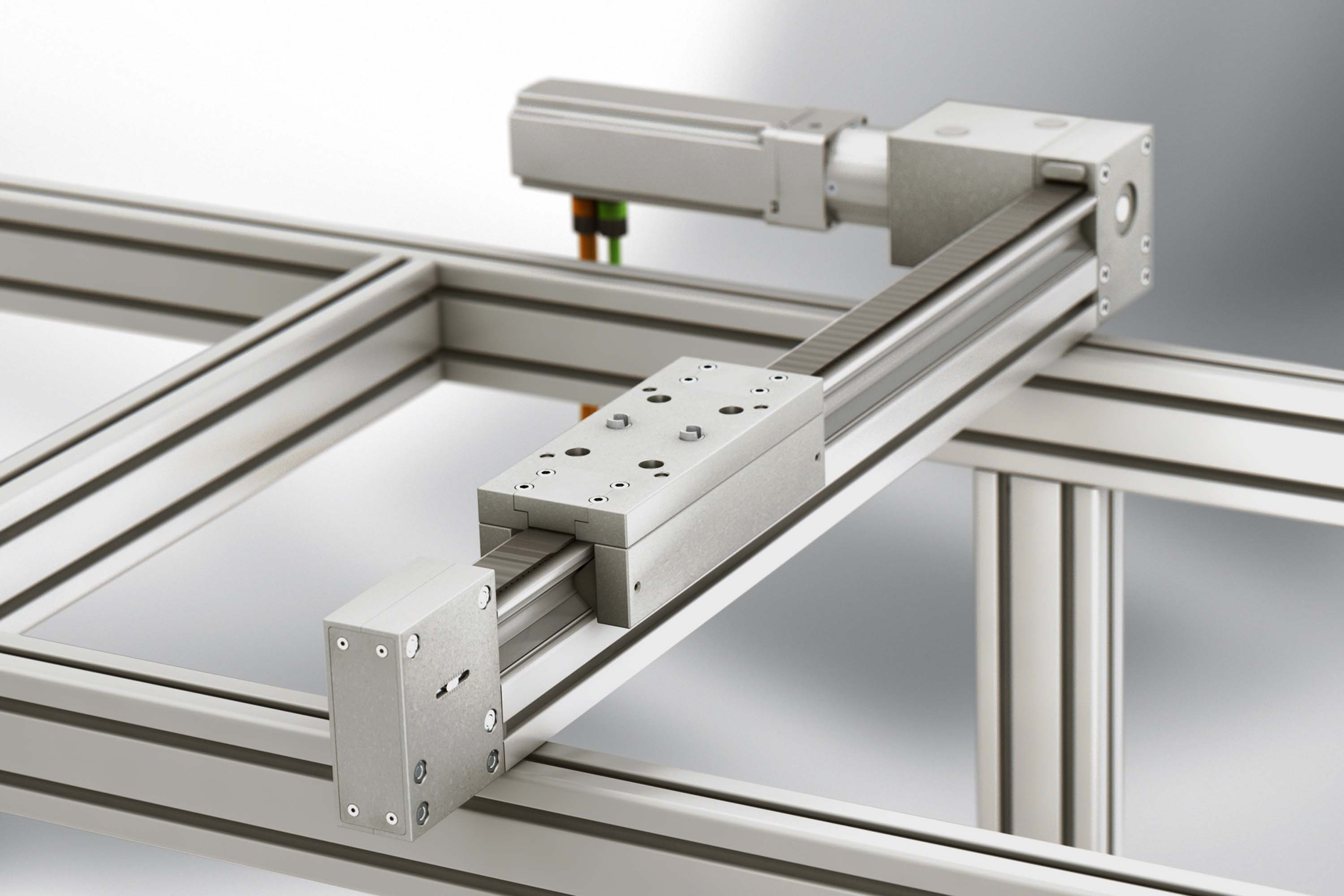
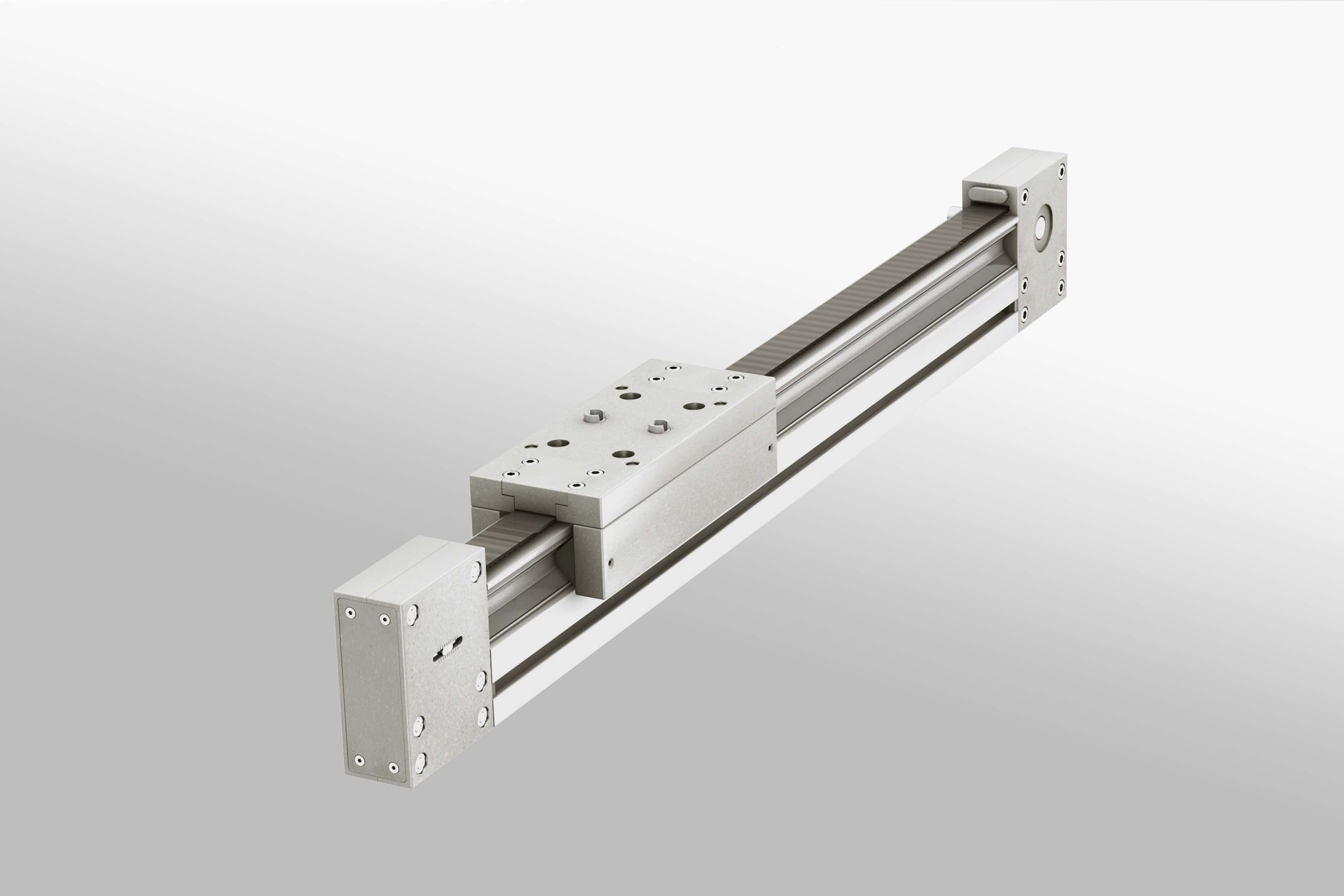
The compact Roller Guide with the best load-to-size ratio of all item drive elements.
•
•
•
•
•
•
•
•
•
•
•
•
•
•
•
•
Linear Unit KRF is augmented by a range of useful accessories that enable simple attachment of slide constructions and drive modules.

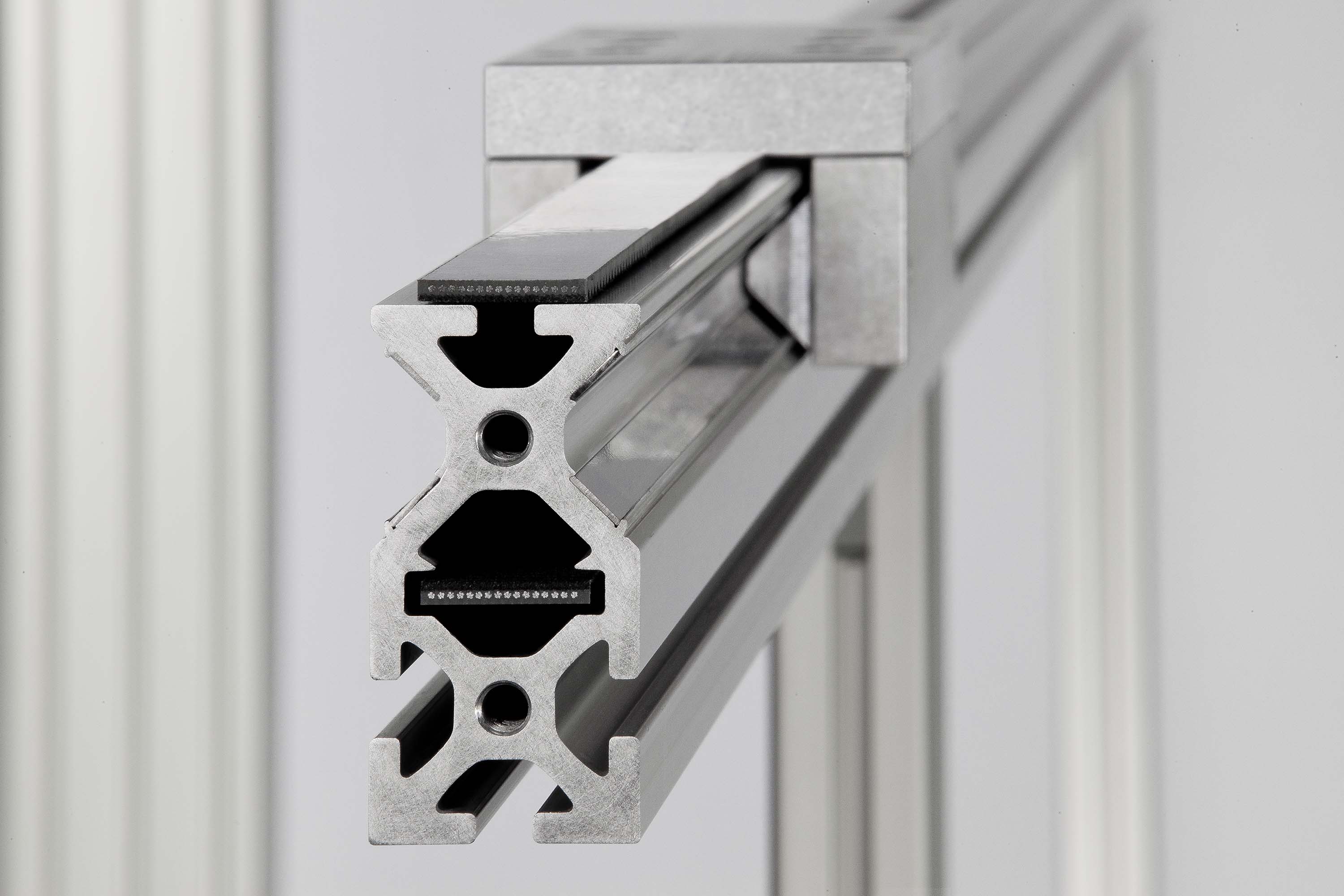
Eight rollers, arranged play-free in a criss-cross pattern, ensure maximum load-carrying capacity with compact size.

The maximum deflection, fmax of the system is governed by the dimension of the profile cross-section, the free profile length and the force applied. It should not exceed 1mm/m. The KRF profile must be given appropriate support if the linearity of movement has to be very precise.

Complete Linear Units with variable stroke length (H), Drive Unit and Reverse Unit, support profile with integrated Roller Guide on guide tracks, preset free of play. Timing-belt tensioning device integrated into Reverse Unit, ball-bearing-mounted pulleys.
Guide slide with eight-piece roller-bearing mounting, oil-lubricated roller contact (re-lubrication every 6 months or every 2500 km)
Acceleration: max. 10 m/s²
Stroke velocity: max. 10 m/s
Stroke velocity: max. 10 m/s
Linear Unit KRF boasts exceptional precision and low-vibration linear movement. Repeat accuracy is ± 0.1 mm.
The mass of a Linear Unit KRF can be determined from the stroke length (without payload):
m = m1 + H x m2


Load specifications

Maximum possible acceleration in relation to moved mass and installation orientation
h = horizontal orientation
v = vertical orientation
v = vertical orientation

Travel speed v in relation to input speed n (timing-belt drive)

Operational force Fx dependent on input torque M (timing-belt drives Fx > 500N)
